Introducing the biggest obstacle
Have you ever wondered why most subwoofers fail to reproduce music accurately? One of the main causes of this problem are memory effects. While good driver design can help, the only practical and effective way to significantly reduce this problem is to use a closed loop servo system.
Memory effects can introduce distortion components which are not represented in harmonic distortion tests. This is one reason why distortion tests don't tell the entire story when it comes to subwoofer accuracy. A subwoofer which has the lowest measured harmonic distortion won't necessarily be the most accurate. We're not simply interested in building subwoofers with the best numbers - we are committed to bringing the most accurate subwoofers possible considering all significant areas of performance.
Memory effects in transducers are the number one obstacle to achieving higher fidelity sound. This is because the sound signal is dynamic. A low level signal following a large signal can be easily masked and modulated by the memory effect left in the system by the large signal. As a result, the low level resolution is compromised. Often this is described as the system being "slow", and unable to keep up with the front speakers.
There are two types of memory effects - mechanical and thermal. Our Direct Servo technology effectively reduces both. Our Direct Servo products are unique in this regard - conventional subwoofers fail by design to address these issues at all.
Thermal Memory
Many audiophiles are aware of the concept of thermal compression, which refers to the loss of efficiency of a driver with the increase of power as the voice coil heats up and causes the voice coil resistance to change. Thermal memory is not as commonly understood. The following chart gives an illustration.
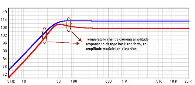
Fig 1.0 - temperature effects on frequency response
The above graph shows how temperature affects the frequency response of a driver. The blue line shows the response when the voice coil is at room temperature and the red line shows the response when the voice coil is at 300 degrees Celsius. As one can see the output is reduced by up to 6 dB except in the region around the impedance peak. In this particular example, it is around 45 Hz. In addition, the Q value of the bass roll-off is also increased by almost a factor of 2.
The above graph shows how temperature affects the frequency response of a driver. As one can see the output is reduced by up to 6 dB and the Q value of the bass roll-off is also increased by almost a factor of 2. So thermal compression not only reduces the output, it also changes the Q value of the alignment, and thus the phase angle of the response.
When the thermal compression changes dynamically, it causes both amplitude modulation and phase modulation distortion.
For instance, the above graph shows the frequency response at two different voice coil temperatures. As the temperature changes between low and high, it causes amplitude modulation. This amplitude modulation distortion is not measured in the conventional harmonic distortion measurement. While the above graph does not show the phase response, one can easily understand that similar modulation on the phase angle is also generated, commonly referred to as phase modulation distortion. Phase modulation distortion is also related to Doppler Effect. As the phase modulation distortion occurs, it is often perceived as the movement of sound image.
To be technically correct, there are two components in thermal compression
![]() temperature of the voice coil
temperature of the voice coil
![]() temperature of the magnet.
temperature of the magnet.
The latter can be resolved using Alnico or rare-earth magnets. What Direct Servo subs address is the compression caused by the temperature of the voice coil.
How thermal memory occurs in the voice coil
The thermal memory effect comes about because the heat from the voice coil cannot be immediately dissipated into the air within the driver. Normally a voice coil has several layers of copper wires. The heat is dissipated through the outermost layer into the air and through the innermost layer into the former. This heat dissipation process takes time. Before the heat can be dissipated, the voice coil resistance increases and the output is reduced. After the heat is dissipated, the temperature recovers, the voice coil resistance drops, and the output is regained. The rate of the temperature recovery resembles an RC network discharging the capacitor and therefore can be characterized using a time constant, which we have found to be around 5 seconds without forced ventilation. What makes the problem more complex is at the resonance peak of impedance curve, the power consumption is low, but the cone movement is high. This forced ventilation makes the time constant shorter. As a result, the time constant in the real world is not a time-invariant quantity. At low bass frequencies, the temperature profile of a voice coil resembles a delayed rectified version of the applied signal. At high frequencies on the other hand, the temperature profile resembles a delayed rectified version of the applied signal envelope.
Thermal compression vs thermal memory
Thermal memory occurs any time the cone makes a movement, no matter if the voice coil temperature is high or low. Thermal compression, on the other hand, is worst when the voice coil is at high temperature. So how serious is this memory effect? A simple mathematical calculation can give us some ideas. The heat specific of copper is 0.4 joule/(g x degrees Celsius). A typical copper voice coil weighs about 50g. 200 watts RMS power (less than half of the full power of today's amplifiers) in one second generates energy of 200 joules. That means an input power of 200 watts RMS in one second will increase a typical voice coil temperature by 10 degrees Celsius. In 2 seconds the temperature increases by 20 degrees Celsius. For every 20 degrees Celsius increase in temperature, the output is reduced by 7%. If the voice coil changes within a range of 20 degrees Celsius, the amplitude modulation distortion is around 7%. The thermal memory effect manifests as a side-band energy in the frequency domain, similar to those generated by jitters and wobble tone. Figure 1.1 and 1.2 show the time domain and frequency domain plots, respectively.
Fig 1.1 - Thermal compression (non servo sub)
The above is the actual microphone measurement of thermal compression on a supposedly constant 60 Hz sine wave using a 370W RMS non servo subwoofer operating at half power, i.e., 200WRMS. The thermal compression is -2%/sec. In 6 seconds, the output is reduced by 12%.
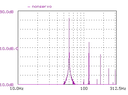
Fig 1.2 - Thermal compression (non servo sub) in the frequeny domain
The frequency domain plot of Figure 1.1.
Notice the strong side-band energy on both sides of 60hz. There is
also some side-band energy around 120hz.
Thermal compression is not the same as amplifier overload. It happens at all power levels with the worst at full power. The root cause is the voice coil being heated up and voice coil resistance increased as a result. It is this type of variation that makes the non servo subs not only sound "compressed", but also less coherent (that is, it is not a time-invariant system). In the following is the same measurement with our Direct Servo sub, same 200WRMS operating power. There is absolutely no thermal compression because the servo loop enable the power amplifier to supply more power to the subwoofer driver to sustain the output level. Figure 1.3 and 1.4 show the time domain and frequency domain plots, respectively.
Fig 1.3 - Thermal compression (Direct Servo sub)
The above is the actual microphone measurement of thermal compression with the same conditions as 1.1. This chart shows that the thermal compression is completely eliminated.
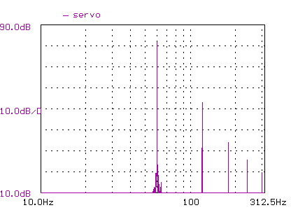
Fig 1.4 - Thermal compression (Direct Servo sub) in the frequency
domain
The frequency domain plot of Figure 1.3.
Notice the side-band energy on both sides of 60hz is greatly reduced.
Mechanical Memory - hysteresis
The best example is the hysteresis effect of a spider, as shown in the charts below. If one stretches a spider and then lets it go (that is, no force), the spider will not immediately return to zero position. It takes a finite amount of time to return to zero. When the signal is repetitive, the relation between force and displacement shows a hysteresis loop. The hysteresis loop has nothing to do with the non linearity of the spider. It is a problem inherent in the shape and form of all spiders. Other components in a driver that exhibit hysteresis, though a full discussion of hysteresis effects in driver components is beyond the scope of this discussion. As ever increasing excursion requirements necessitate larger and larger spider, this inherent hysteresis effect can only get worse.
Fig 1.5 - Hysteresis loop in a spider
The ability to dramatically reduce this effect is a unique advantage of Direct Servo Subwoofers. It is not possible to overcome this problem with good driver design, hence even the most expensive drivers will be plagued by this problem.
The effects of mechanical memory are also discussed in our discussion of the benefits of a closed loop servo system compared to an open loop in a conventional subwoofer.
Direct Servo Subwoofers
The following figure shows the connection between a Direct Servo amplifier and driver. It is a closed loop system in which there is a servo (or velocity) feedback from the driver to the amplifier so the amplifier will linearize the velocity of the cone movement, instead of just at the amplifier output. At any time when the velocity signal deviates from the expected value, the amplifier will adjust its output to correct it. As a result, this arrangement offers additional distortion reduction that is not available in conventional open-loop subwoofers.
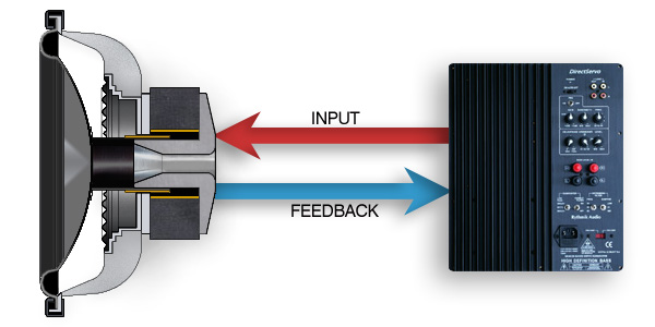
Fig 1.6 - Direct Servo closed loop diagram
The input (shown red) is connected to the voice coil as with a conventional subwoofer. The feedback from the sensing coil (shown blue) closes the loop. This allows corrections to be made, and allows for a much greater degree of control.
Benefits:
![]() Frequency response is independent of voice coil resistance
Frequency response is independent of voice coil resistance
![]() Spider and surround distortion reduced by 6 - 9 dB
Spider and surround distortion reduced by 6 - 9 dB
![]() No thermal induced distortion
No thermal induced distortion
The frequency response of Direct servo subs is almost independent of the voice coil resistance/temperature. To demonstrate this, we add a serial resistor of 3ohms to the driver to emulate a scenario where the voice coil temperature increases to 300 Celsius and then compare it with the frequency response without this 3ohm resistor. The volume control is at exactly the same position for both cases. The two curves are plotted below (Fig 1.7). They almost track each other. The actual difference between the two curves is less than 0.2 dB whereas in non servo subs, the difference can be up to 6 dB as we have previously demonstrated. As a result, not only do Direct servo subs maintain the same frequency response over any voice coil temperature, they do not have any thermal-induced memory distortion either.
Fig 1.7 - Direct Servo with and without a 3 ohm resistor
added
This chart shows how Direct Servo is able to overcome any changes in voice coil resistance. Two plots are overlaid, one with a 3 ohm resistor added. The two plots vary by less than 0.2 dB. As shown previously, this would cause a non servo subwoofer to vary by up to 6 dB.
Distortion Reduction
To demonstrate the distortion reduction capability of Direct Servo subs on spider non linearity and memory effect, we set up a 2 cu ft sealed box with our DS12TC driver* in both non servo and servo configurations (Fig 1.8). The test signal is a 10 Hz sine wave that produces 1/4" peak-to-peak excursion.
The purpose is to examine the low level distortion characteristics. At this excursion level, the distortion is mainly caused by the non linearity in the spider and surround. The results are plotted below. Each horizontal division is 10 Hz. The results for the non servo and servo are offset horizontally to provide a better visual comparison. In reality, both of them use the same 10 Hz sine wave and produce the same excursion. The distortion reduction of the Direct servo sub for the 2nd, 3rd, 4th, and 5th harmonic distortion is 3db, 5db, 8db, and 5db, respectively.
One thing to note is the 2nd order harmonic distortion at 20 Hz is mainly due to flux modulation with low memory effect. Also the 2nd order harmonic distortion is less audible than higher order distortions. Also worth noting is that dB scale is logarithmic so that a difference of 5 dB is a factor of 3x in terms of power whereas a difference of 8 dB is a factor of 6x in terms of power. The ability of the Direct Servo subs to reduce harmonic distortions above 2nd order is an indication of their ability to reduce the non linearity of the spider, including the memory effect. The actual mechanism by which Direct Servo subs achieve this distortion reduction is through servo feedback. If the cone velocity (and therefore position) deviates from the expected value, additional power will be supplied by the amp to force the cone to follow the correct velocity and therefore reduce distortion.
Fig 1.8 - Low frequency distortion comparison - servo vs
non servo
This chart shows how Direct Servo reduces harmonic distortion. It is based on a 10 Hz sine wave where the first two spikes on the left show the amplitude of the original tone - equal for both servo and non servo. The next two spikes represent 2nd order harmonic distortion (20 Hz), followed by 3rd, 4th, 5th and 6th order. The distortion reduction of the Direct servo sub for the 2nd, 3rd, 4th, and 5th harmonic distortion is 3db, 5db, 8db, and 5db, respectively.
Since the isolation between the amplifier and the driver in non servo subs is the largest when the voice coil temperature is high, one can expect that distortion is subsequently higher. After we put in a series resistor of 3ohms to the driver to emulate the high voice coil temperature scenario, the new results are plotted below. The distortion reduction of Direct servo sub for the 2nd, 3rd, 4th, and 5th harmonic distortion is 3 dB, 8 dB, 14 dB, and 6 dB, respectively. Again, as the dB scale is logarithmic, a 14 dB difference is a factor of 16x in terms of power. The improvement over the room temperature case is mainly because the distortion increases in the non servo setup. Again, in the Direct servo sub, the distortion is hardly affected by the voice coil temperature.
Fig 1.9 - Distortion comparison at high temperature- servo
vs non servo
This test is the same as the previous except a 3 ohm resistor is added to emulate the effects of the voice coil heating up. The non servo subwoofer now goes up in distortion more, but Direct Servo is much less affected. The distortion reduction of Direct servo sub for the 2nd, 3rd, 4th, and 5th harmonic distortion is 3 dB, 8 dB, 14 dB, and 6 dB, respectively.
While so far we have only discussed the distortion reduction part of our servo sub, in reality our servo subs also have higher usable output than conventional non-equalized servo subs.
The secret is discussed in our article on smart Q.
To summarize, Direct Servo offers the following benefits:
![]() No voice coil thermal-induced compression or distortions.
No voice coil thermal-induced compression or distortions.
![]() Spider and surround distortion reduced by 6 - 9 dB
Spider and surround distortion reduced by 6 - 9 dB
![]() Flat frequency response that is less dependent on T/S parameters.
Flat frequency response that is less dependent on T/S parameters.
![]() Audiophile bass sound at an affordable price: articulate, tight, transparent, and well-defined bass
Audiophile bass sound at an affordable price: articulate, tight, transparent, and well-defined bass
![]() Applicable to all subwoofer configurations (including horns, dipole, infinite baffle and others)
Applicable to all subwoofer configurations (including horns, dipole, infinite baffle and others)
![]() Higher output (with better excursion utilization) for sealed, IB, and Dipole subs.
Higher output (with better excursion utilization) for sealed, IB, and Dipole subs.
* Please note: this driver has now been replaced with a new model (DS1200). All comments still apply to our current models.